Affiliated A
(Specific appendix)
Design verification test
A.1 The test required
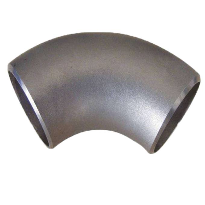
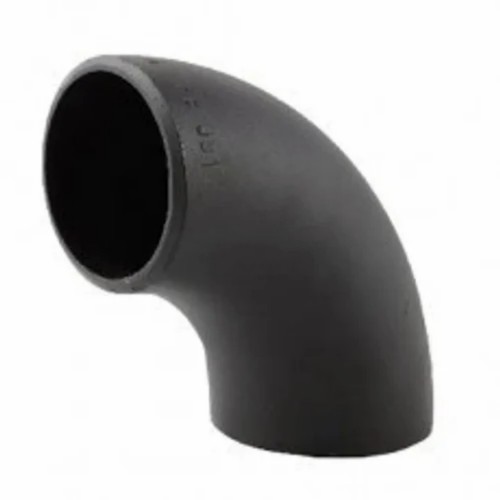
When the manufacturer uses the verification test method to identify the design of the pipe parts, the verification test shall be performed in accordance with the provisions of this appendix.The test should be carried out in accordance with the tube parts specified in A.3 and the blasting pressure calculated by the pipelines connected to it.The special angle of the factory manufactured, its geometric shape is similar to the 90 ° elbow of the test, and does not need to be tested separately.The edge short section is exempted from verification test, because they are used in the installation of flange and have different rated values according to the conditions of use.

A.2 Test assembly part
A.2.1 sample parts
The test pipe parts should be selected from the pipes with the same basic design shape and manufacturing method, and are required to be verified materials and furnace batch numbers in accordance with the regulations of GB/T13401, including heat treatment.The test pipe parts should be checked by size and complies with this standard.
The computational blasting pressure should be at least computational with A.3. The verification test pressure of the same size seamless pipe or welding tube section welded to each end of the test pipe part.The pipe section can be thicker than the nominal wall of the pipeline logo, but it should not exceed 1.5 times that of the wall thickness of the pipeline logo.When the faulty edge of any inner circle is greater than 1.5mm, the internal tapered cone hole with a slope should be used to reduce its internal error edge.The interception length of the pipe section should be as follows:
a) For pipes from DN350 (NPS14) and below, the minimum length of the tube should be an outer diameter.
b) For pipes greater than DN350 (NPS14), the minimum length of the tube should be half of the outer diameter of the tube.
The test fluid should be water or other liquid.Copy the water pressure of the test assembly.It is recommended to perform at least 3 sample tests for each test pipe part.When the number of samples of the test is different, select the test coefficient F used in Table A.1 to select the test pressure calculation formula (A.1)
Note: It complies with different caliber and wall -thick pipe samples (e.g., 2 or 3 pieces of 90 ° long radius elbow) specifically similar to the geometric shape specified in A.4, which can determine the test coefficient of a set of pipes.
The test should be performed by the pipeline rupture or maintained (or exceeds) the minimum verification test pressure calculated by the formula (A.1) at least 3 minutes.For each test, if the test assembly can withstand at least equal to the minimum calculation verification test pressure value without rupture, the test is qualified.
p = 2st d f …………………………………… (A.1)
In the formula:
P —— The minimum calculation verification test pressure of the pipe parts, the unit is the Semopa (MPA);
S ——— The actual tensile strength measured on the sample of the test pipe parts should meet the tensile strength required by the tube component material level specified in the corresponding specifications.
T —— The nominal wall thickness of the tube marked on the pipe part, the unit is millimeter (mm);
D —— The outer diameter of the specified tube, the unit is millimeter (mm);
f ——The test coefficient, see Table A.1, countless outline.
Post time: Jan-05-2023


